How to Build a MIDI Controller With Arduino: Parts, Wiring and Code
Two buttons wired to a breadboard do nothing in your music software, and the real puzzle is how to build a MIDI controller that it will actually recognize.
The catch is the board rather than the buttons, because the easy route needs native USB, and the classic Arduino Uno doesn’t have it.
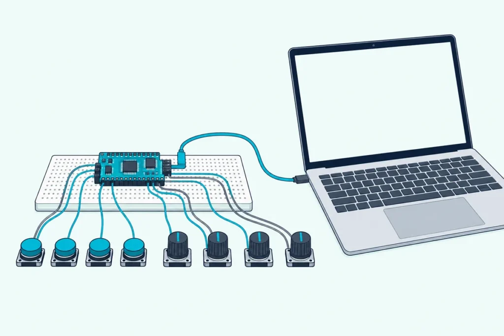
This guide builds a four-button, four-knob controller on a Leonardo or Micro, using Arduino’s own documentation and the MIDI Association’s specifications.
You’ll get a parts list, wiring for buttons and knobs, a sketch that follows Arduino’s own example, and the settings that make Ableton, Reaper and FL Studio see it.
Begin with the big picture, because the board you pick in step one decides how every later step works.
How to Build a MIDI Controller: The Six Steps
Here’s the whole job in one pass, so the later sections have somewhere to hang their details.
An Arduino MIDI controller is a circuit that watches buttons and knobs and turns each change into a MIDI message. The board sends those messages to your computer over USB, and your music software treats them like the output of any store-bought controller.
- Pick a board with native USB: a Leonardo, a Micro, a Pro Micro or a Teensy.
- Gather the parts: buttons, 10k potentiometers, jumper wires and a breadboard.
- Wire the buttons to digital pins and the knobs to analog pins.
- Install the MIDIUSB library and upload the sketch.
- Switch the board on as a MIDI input in your music software.
- Mount everything in a case once it works on the breadboard.
Steps two through five can happen on a solderless breadboard, which lets you rewire freely until everything behaves.
Step six waits until the controller works, because drilling holes for parts that misbehave is the expensive way to find out.
If the vocabulary is new, our plain-English MIDI controller explainer covers it before you pick up a wire.
Which Arduino Board Can Send MIDI Over USB?
That first step comes down to one feature, native USB, which the Leonardo and Micro have and the classic Uno doesn’t.
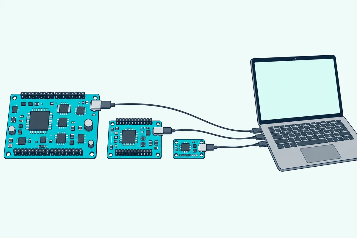
Arduino says the Leonardo’s ATmega32U4 chip has built-in USB communication, which removes the need for a secondary processor. The Uno and other boards use separate microcontrollers for running sketches and for USB, according to Arduino’s getting-started guide for the Leonardo and Micro.
The MIDIUSB library, credited to Gary Grewal and Arduino, says it supports only boards with native USB capabilities and names the Leonardo, Micro, Due and Zero as examples. Its properties file lists the avr, sam and samd architectures, so a board built on another chip family needs a check of the library’s page before you buy.
| Board | Native USB? | How it sends MIDI | Analog inputs | Good fit for |
|---|---|---|---|---|
| Arduino Leonardo | Yes | MIDIUSB library | 12 | A first build with socket headers |
| Arduino Micro | Yes | MIDIUSB library | 12 | A breadboard or a slim case |
| Pro Micro (ATmega32U4) | Yes | MIDIUSB library | 4 labeled | A low-cost board for a small controller |
| Arduino Uno R3 | No | Serial bytes plus a bridge program | 6 | A board you already own |
| Teensy 4.0 | Yes | Teensyduino’s usbMIDI functions | 14 | Many controls or fast response |
The analog counts come from Arduino’s analogRead reference for the Uno, Leonardo and Micro, from PJRC for the Teensy and from HiLetgo’s listing and board photos for the Pro Micro. Three of these boards run this guide’s sketch as written, and each one sells on Amazon in a form that suits a first build.
The Arduino Leonardo has 20 digital pins, 12 analog inputs, a 16 MHz crystal, a micro-USB port, a power jack and a reset button, according to Arduino. Its socket headers take jumper wires directly, which makes it the simplest board to start wiring.
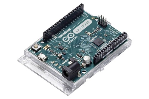
The Arduino Leonardo
The Arduino Micro is the same ATmega32U4 design in a form factor that Arduino says is easy to place on a breadboard. It has the same 20 digital pins and 12 analog inputs as the Leonardo, so this guide’s sketch runs on either one.
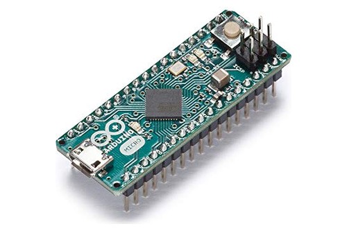
The Arduino Micro
The HiLetgo three-pack of Pro Micro boards runs an ATmega32U4 at 5 volts and 16 MHz with an on-board micro-USB connector, according to HiLetgo’s listing. Its gallery shows the Arduino IDE set to the Leonardo board, and the photos show the header strips separate from the board, so plan to solder them.
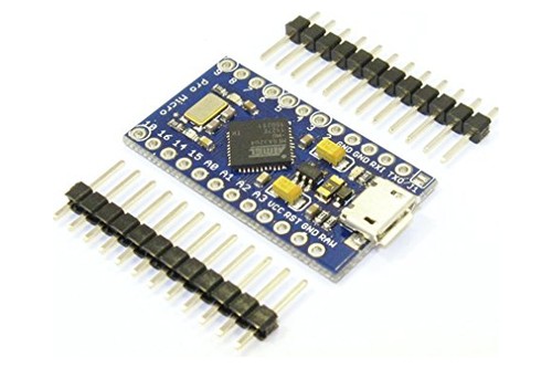
The HiLetgo three-pack
Get Studio Tips Weekly
Join 5,000+ creators getting acoustic treatment advice every week.
No spam. Unsubscribe anytime.Should You Use a Teensy Instead?
The table above shows why some builders look at a Teensy: it has more analog inputs, and it skips the MIDIUSB library altogether.
PJRC says that choosing MIDI from the Tools > USB Type menu turns a Teensy into a USB MIDI device, and that Teensy 2.0, Teensy++ 2.0, Teensy LC and Teensy 3.0 to 4.1 are supported. It describes the result as a class-compliant device that can work with the built-in drivers on all major operating systems.
Sending takes one line per message, such as usbMIDI.sendNoteOn(60, 99, 1) for note 60 at velocity 99 on channel 1 and usbMIDI.sendControlChange(16, 64, 1) for controller 16 at value 64. PJRC’s examples number channels from 1 while MIDIUSB counts from 0, so adjust the channel number when you move code between the two.
The Teensy 4.0’s pins accept 0 to 3.3 volts and aren’t 5-volt tolerant, according to PJRC, so wire knobs to its 3.3-volt pin rather than to 5 volts. PJRC also says a controller that only transmits should read and discard incoming messages with while (usbMIDI.read()) {}, which keeps the USB buffers from filling with messages nobody reads.
For bigger builds, PJRC’s page points to a MIDIcontroller library with easy-to-use functions for buttons, knobs and encoders.
The Teensy 4.0 without pins runs an ARM Cortex-M7 at 600 MHz with 40 I/O pins and 14 analog inputs, according to PJRC. It programs from the Arduino IDE with PJRC’s Teensyduino add-on, and this listing is the no-pins version, so header pins or wires need soldering.
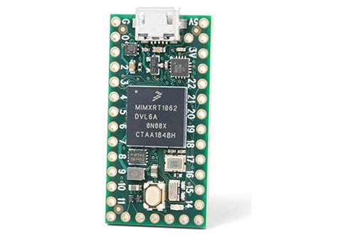
The Teensy 4.0 without pins
What Parts Do You Need for an Arduino MIDI Controller?
Once the board is chosen, the rest of the parts list is short.
Beyond the board, four kinds of part do almost all the work: buttons for notes, potentiometers for knobs and faders, wire to join everything, and a USB cable.
| Part | What it does | What to look for |
|---|---|---|
| Board | Reads the controls and sends MIDI | Native USB, as covered above |
| USB cable | Powers the board and carries the MIDI | A data cable that matches the board’s port, not a charge-only one |
| Momentary buttons | One note each | Arcade buttons with microswitches or small tactile buttons |
| 10k potentiometers | One knob or fader each | Linear taper and 10k ohms, the value Arduino’s own tutorials use |
| Breadboard and jumper wires | Join everything without solder | A full-size breadboard and a mixed pack of wires |
| Enclosure | Holds it all | A project box, a wooden panel or a 3D print |
Arduino’s Help Center lists a charging-only USB cable among the common reasons a board never shows up, which is why the cable gets its own row.
The Easyget six-pack of 30 mm arcade buttons mounts in a 28 to 32 mm hole, and its listing claims 10,000,000 cycles of microswitch reliability. Each button ends in a .187 inch (4.8 mm) terminal, so wire it with matching connectors or solder wires to the tabs.
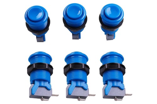
The Easyget six-pack of 30 mm arcade buttons
The Zovfam B10K kit holds 20 linear 10k potentiometers with 20 nuts, 20 washers and 20 caps in a plastic box, according to Zovfam’s listing. The shaft is knurled and the listing gives the length as 31 mm, so four of them cover this guide’s controller with sixteen to spare.
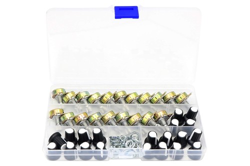
The Zovfam B10K kit
Buttons and potentiometers can be any size that fits your layout, because the board only sees a switch closing or a voltage changing.
What Does an Arduino Actually Send to Your Computer?
That parts list maps onto just two kinds of MIDI message, and both are simple enough to read by eye.
According to the MIDI Association’s message summary, a Note On carries a note number and a velocity, while a Control Change carries a controller number from 0 to 119 and a value from 0 to 127. A Note Off ends the note, so every button needs both.
Every message also names a channel, which the MIDI Association’s table stores as 0 to 15 and software shows as 1 to 16. The comments in Arduino’s MIDIUSB example make the same point, and it’s why the sketch below sets its channel to 0.
| Control | Message it sends | What you set in the sketch |
|---|---|---|
| A button | Note On when pressed, Note Off when released | A note number from 0 to 127 and a velocity |
| A knob or fader | Control Change whenever it moves | A controller number and a value from 0 to 127 |
Buttons become notes because software instruments and drum pads respond to notes, and knobs become controller numbers that your software can link to almost any parameter.
The MIDI Association lists controller numbers 16 to 19 as general purpose controllers and 20 to 31 as undefined, so they’re free for knobs, while 7 and 10 already mean volume and pan.
Inside the MIDIUSB library, each message travels as a four-byte packet whose first byte names the event type, such as 0x09 for note on, 0x08 for note off and 0x0B for control change. The second byte combines the status with the channel, and the last two carry the note and velocity or the controller and value, following Arduino’s own example.
How Do You Wire Buttons to the Board?
Buttons are the easier half, because the board can supply its own pull-up resistor.
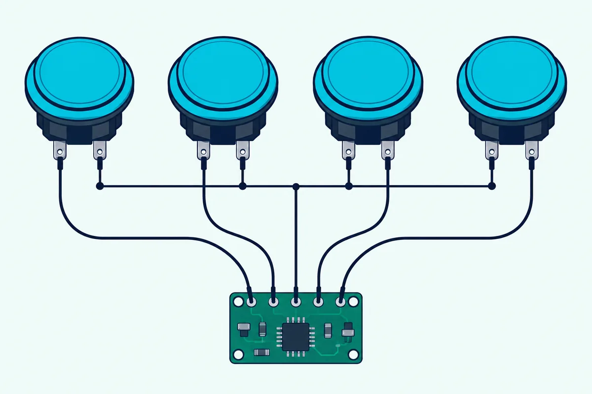
Wire each button between a digital pin and ground and switch on INPUT_PULLUP for that pin in the sketch, which means no external resistor is needed. Arduino’s Digital Pins guide says the ATmega chip has built-in pull-up resistors of roughly 20 kilohms, so the pin reads HIGH while the switch is open and LOW while it’s pressed.
The MIDI Association’s own Arduino build article says the same about its arcade buttons, noting that the internal pull-ups remove the need for a resistor on each one.
| Button | Board pin | Other leg | Note it sends |
|---|---|---|---|
| 1 | 2 | Ground | 36 |
| 2 | 3 | Ground | 37 |
| 3 | 4 | Ground | 38 |
| 4 | 5 | Ground | 39 |
Run a wire from the board’s GND pin to a breadboard rail and tie each button’s second leg to that rail, so all four share one ground.
Wikipedia’s entry on the miniature snap-action switch, the microswitch inside an arcade button, labels its contacts common, normally open and normally closed. Wire the common terminal and the normally open one, so the circuit closes only while the button is pressed.
Skip pin 13 for buttons, because Arduino’s Digital Pins guide says an enabled pull-up there hangs at about 1.7 volts on most boards and always reads LOW. PJRC gives the same warning for the Teensy, saying INPUT_PULLUP shouldn’t be used with pin 13.
Where Do Knobs and Faders Connect?
Knobs are the other half, and they need three wires each instead of two.
A potentiometer has three terminals, and Arduino’s analogRead reference wires it with the middle terminal, the wiper, to an analog pin and the outside leads to ground and +5V. Turning the knob moves the voltage at the wiper, and the board’s 10-bit converter turns that voltage into a number from 0 to 1023.
| Knob | Analog pin | Controller it sends |
|---|---|---|
| 1 | A0 | 16 |
| 2 | A1 | 17 |
| 3 | A2 | 18 |
| 4 | A3 | 19 |
Connect every knob’s outer legs to the board’s 5-volt and ground pins, which are labeled 5V and GND on a Leonardo or Micro and VCC and GND on a Pro Micro. Swap those two wires on any knob that turns the wrong way.
A 10-bit reading has 1,024 steps and a MIDI value has 128, so the sketch divides by eight with raw >> 3, which maps 1,023 to exactly 127. Every MIDI value then covers eight readings, and the top and bottom of the turn land on 127 and 0.
Arduino’s map() does a similar job, but it uses integer math and truncates fractions, so map(1020, 0, 1023, 0, 127) returns 126 and a knob that stops short of 1,023 can never reach 127. The reference also says map() doesn’t constrain values and points to constrain() for that.
Sliding faders are potentiometers too, so they take the same three wires, but check the listing or the markings on the part to see which terminal is which. On a Teensy, connect the outer legs to 3.3 volts and ground instead, because PJRC says its analog range is fixed at 0 to 3.3 volts.
Leave no analog pin in use unconnected, because Arduino’s analogRead reference says an unconnected pin returns values that fluctuate with the other inputs and even with how close your hand is to the board.
What Does the Finished Sketch Look Like?
With the wiring done, the sketch turns those pin changes into the messages from the table above.
Install the MIDIUSB library first: in Arduino IDE 2, click the library icon in the left column, search for MIDIUSB and click Install, as Arduino’s library guide describes. Then choose your board under Tools and open a new sketch.
The sketch follows the pattern in Arduino’s own MIDIUSB example, with three small functions that build the packets and two loops that watch the buttons and the knobs.
#include "MIDIUSB.h"

// 0 is channel 1 in your software
const byte CHANNEL = 0;
const byte NUM_BUTTONS = 4;
const byte NUM_KNOBS = 4;

const byte buttonPins[NUM_BUTTONS] = {2, 3, 4, 5};
const byte buttonNotes[NUM_BUTTONS] = {36, 37, 38, 39};
const byte knobPins[NUM_KNOBS] = {A0, A1, A2, A3};
const byte knobControls[NUM_KNOBS] = {16, 17, 18, 19};

const unsigned long DEBOUNCE_MS = 10;
const int KNOB_THRESHOLD = 4;

bool buttonDown[NUM_BUTTONS];
unsigned long lastChange[NUM_BUTTONS];
int lastRaw[NUM_KNOBS];

void noteOn(byte channel, byte pitch, byte velocity) {
  byte status = 0x90 | channel;
  midiEventPacket_t event = {0x09, status, pitch, velocity};
  MidiUSB.sendMIDI(event);
}

void noteOff(byte channel, byte pitch, byte velocity) {
  byte status = 0x80 | channel;
  midiEventPacket_t event = {0x08, status, pitch, velocity};
  MidiUSB.sendMIDI(event);
}

void controlChange(byte channel, byte control, byte value) {
  byte status = 0xB0 | channel;
  midiEventPacket_t event = {0x0B, status, control, value};
  MidiUSB.sendMIDI(event);
}

void setup() {
  for (byte i = 0; i < NUM_BUTTONS; i++) {
    pinMode(buttonPins[i], INPUT_PULLUP);
  }
  for (byte i = 0; i < NUM_KNOBS; i++) {
    lastRaw[i] = analogRead(knobPins[i]);
  }
}

void readButtons() {
  for (byte i = 0; i < NUM_BUTTONS; i++) {
    bool pressed = (digitalRead(buttonPins[i]) == LOW);
    bool changed = (pressed != buttonDown[i]);
    bool settled = (millis() - lastChange[i] >= DEBOUNCE_MS);
    if (changed && settled) {
      buttonDown[i] = pressed;
      lastChange[i] = millis();
      if (pressed) {
        noteOn(CHANNEL, buttonNotes[i], 100);
      } else {
        noteOff(CHANNEL, buttonNotes[i], 0);
      }
      MidiUSB.flush();
    }
  }
}

void readKnobs() {
  for (byte i = 0; i < NUM_KNOBS; i++) {
    int raw = analogRead(knobPins[i]);
    if (abs(raw - lastRaw[i]) >= KNOB_THRESHOLD) {
      lastRaw[i] = raw;
      controlChange(CHANNEL, knobControls[i], raw >> 3);
      MidiUSB.flush();
    }
  }
}

void loop() {
  readButtons();
  readKnobs();
}
Each button sends a Note On at velocity 100 when pressed and a Note Off when released, and the 10-millisecond lockout ignores the chatter a mechanical switch makes. A plain switch can’t tell how hard you pressed it, so every note goes out at the same velocity.
Each knob sends a Control Change only when its reading has moved by at least four steps, which is half of one MIDI step and keeps small electrical noise off the wire. Setup reads every knob once first, so nothing is sent when you plug the board in.
MidiUSB.flush() follows each message, as it does in Arduino’s example, so the queued packet goes out over USB. To change what a control sends, edit the buttonNotes and knobControls lists, because each entry lines up with the pin in the same position.
Why Do Buttons Double-Fire and Knobs Jitter?
Even a correct sketch can misbehave, because real switches and real potentiometers are noisy.
Arduino’s Debounce tutorial says pushbuttons often generate spurious open and close transitions when pressed, which a program can read as several presses in a very short time. Its fix is to check twice within a short period, using millis() to keep track of the time.
The sketch above uses a simpler lockout, ignoring a button for 10 milliseconds after each change. PJRC’s Bounce example uses 5 milliseconds and calls that appropriate for good-quality mechanical pushbuttons, so 10 leaves room to spare, and you can raise DEBOUNCE_MS a few milliseconds at a time if a cheap button still chatters.
Knobs jitter for a different reason: the converter reads a slightly different number each time, even when your hand is still. The KNOB_THRESHOLD of 4 absorbs that, and raising it to 6 or 8 calms a noisy pot at the cost of a coarser first response.
If a knob still flickers, Arduino’s Smoothing tutorial shows a running average that stores the last ten readings in an array and divides their sum. It says a larger numReadings smooths the data even further, which makes it the next step up if the threshold alone isn’t enough.
Keep delay() out of the main loop, because every pause is a stretch during which no button or knob is being read. Arduino’s analogRead reference gives about 100 microseconds per read on ATmega boards, so the four knobs here take roughly 0.4 milliseconds per pass, which leaves plenty of time for everything else.
To watch the raw numbers, add Serial.begin(9600) to setup() and Serial.println(raw) to readKnobs(), then open the Serial Monitor. Arduino’s Leonardo and Micro guide adds that the Serial Monitor slows down when fed continually, so put a delay(1) after the print while you test and remove it afterward.
How Does Your Computer Find the Controller?
Once the sketch is uploaded, the board shows up on its own as a MIDI input, and your software only has to be told to listen.
The MIDIUSB README says the library lets an Arduino act as a MIDI instrument over USB, and its own Linux test lists the result as a port named Arduino Micro MIDI 1. Expect your software to list the board under a similar name, such as Arduino Micro MIDI 1 in that test, in its MIDI input list.
Arduino’s guide for the Leonardo and Micro says drivers should install automatically, but some Windows versions show Unknown USB device, and its driver-installation guide covers that case. On any system, a board that never appears usually points to the cable or the port, which the troubleshooting section below walks through.
Ableton Live
Start in the Link, Tempo & MIDI tab of Live’s Settings, which Ableton’s manual says opens with Ctrl+comma on Windows or Cmd+comma on a Mac. Ableton’s MIDI controllers FAQ says to activate Track and Remote for the input port connected to the controller, and to activate only the ports you need.
To play an instrument with the four buttons, the FAQ says to set MIDI From to All Ins or pick the board’s port, set Monitor to In or Auto and arm the track. To test, press a button and watch the MIDI input indicators at the top of Live’s window, which the manual says flash whenever Live recognizes an incoming message.
To link a knob to a parameter, press the MIDI switch in the upper right corner, click the parameter, move the knob and press the switch again, as the manual’s mapping steps describe.
REAPER
REAPER’s user guide says to choose Options, then Preferences, then Audio and MIDI Inputs, right-click the device and pick Enable input for track record input. It adds that you should also pick Enable input for control messages if you want the device to act as a controller.
To link a knob to a plug-in control, the guide says to touch the control in the FX window, click the Param button, choose Learn and then twiddle the knob. The guide says absolute mode with soft takeover is appropriate in many cases, and these knobs send absolute values.
FL Studio
FL Studio’s manual says to open Options > MIDI settings, or press F10, select the device in the Input list and click Enable. The MIDI activity light on the Main Panel then blinks each time controller data arrives.
The same page says the Debug log shows the MIDI data FL Studio receives, which it calls useful for learning the CC numbers of controls and for troubleshooting connections. Our guide to assigning controls in FL Studio picks up from there.
Can an Arduino Uno Send MIDI Too?
Yes, but not the easy way, and that’s the difference the board table was pointing at.
An Uno can send MIDI messages as plain serial data, and a program on the computer has to turn those bytes into a MIDI port. That’s the route the MIDI Association’s own Arduino build article takes, with the Hairless MIDI to Serial Bridge and a virtual cable called loopMIDI.
The catch is age: the Hairless page says it’s kept for historical purposes, that its last release came in August 2012 and that it will probably not work on modern operating systems. One Instructables guide reports that the app won’t work on macOS Catalina and later.
If you still want the serial route, the Hairless page lists 115200 bits per second as its default speed, so the sketch sends raw MIDI bytes at that rate:
void setup() {
  // Same speed as the bridge's default
  Serial.begin(115200);
}

void sendMidi(byte status, byte data1, byte data2) {
  Serial.write(status);
  Serial.write(data1);
  Serial.write(data2);
}

void loop() {
  sendMidi(0x90, 60, 100);  // note on, channel 1
  delay(500);
  sendMidi(0x80, 60, 0);    // note off, channel 1
  delay(500);
}
The status byte 0x90 means Note On on channel 1, and the MIDI Association’s Arduino MIDI output article sends the same three bytes with Serial.write(). On a Mac, the bridge and your music software meet at the IAC Driver, which Hairless says you switch on with the Device is online box in Audio MIDI Setup, and on Windows they meet at a loopMIDI port.
If you’d rather not write raw bytes, Hairless’s FAQ points to the Arduino MIDI Library and says its Serial.begin(115200) must come after MIDI.begin().
Switch the bridge off before you upload a new sketch, because Hairless says it needs to be disabled before anything else uses the serial port, including Arduino programming. With that much friction, a Leonardo or Micro is the better buy than a bridge, even if you already own an Uno.
How Can You Add More Controls Than the Board Has Pins?
That’s a fair worry once the first four knobs work, because a Leonardo has 12 analog inputs and a Teensy 4.0 has 14.
A multiplexer is the usual fix, and SparkFun describes its CD74HC4067 breakout as a 16-channel analog and digital multiplexer that lets you connect up to 16 sensors using only 5 pins. You choose a channel by sending its binary address on four digital pins, then read the knob on that channel through one analog pin.
Buttons can share pins too, since a 4 by 4 grid wired as rows and columns needs eight pins instead of sixteen, at the cost of more code to scan it. If pins are still tight after that, PJRC lists the Teensy 4.1 with 55 I/O pins in total and 18 analog inputs.
Can an Arduino Also Drive 5-Pin MIDI Cables?
Yes, and it matters because older synths and drum machines listen on five-pin cables instead of USB.
The MIDI Association’s Arduino MIDI Output Basics builds that output with a DIN socket, two 220-ohm resistors and a 7404 hex inverter, and it sets the serial speed to 31250 baud, the MIDI rate. It also points newcomers to SparkFun’s MIDI Shield as a ready-made version.
On a Leonardo or Micro, the Serial object is the USB connection, and Arduino’s guide says the hardware pins 0 and 1 use Serial1 instead. A five-pin output on those boards therefore starts with Serial1.begin(31250).
Can You Build a MIDI Keyboard the Same Way?
Yes, because a keyboard is just many buttons that each send a different note, and the sketch above already does that for four of them.
A 5 by 5 grid wired as rows and columns reads 25 switches with ten pins, so a two-octave keyboard needs a grid like that or a few multiplexers, plus a sketch that scans it. The gap between this build and a store-bought keyboard is velocity, because plain switches can’t tell how hard a key was struck and every note goes out at the same level.
What Should the Controller Live In?
Only after everything works on the breadboard does a case make sense, and the wiring above decides how much room it needs.
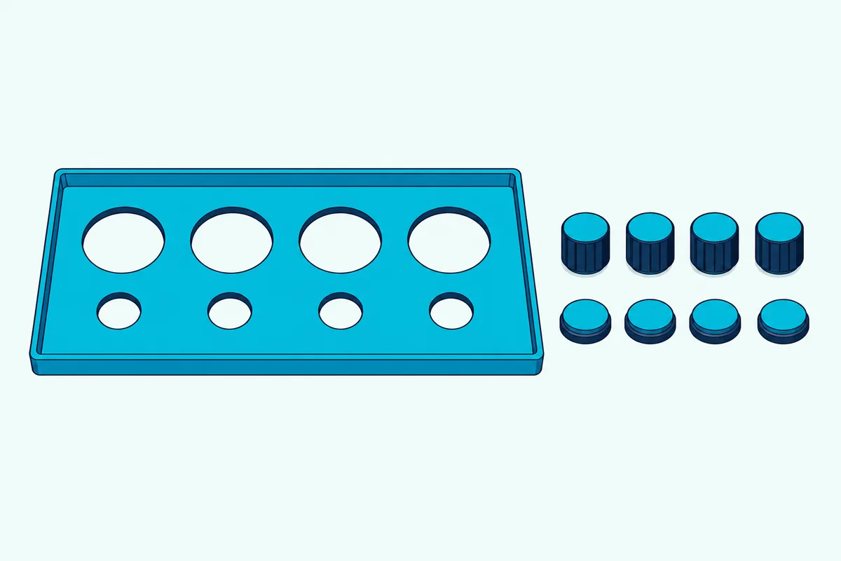
Any rigid box works, such as the wooden case in the MIDI Association’s Arduino build article, as long as the holes match your parts. That article sketches the front panel on paper first, and its 29.7 mm arcade buttons sit in 30 mm holes with the hole centers 40 mm apart, leaving 10 mm between neighbors.
The Easyget buttons above fit a 28 to 32 mm hole according to Easyget’s listing, so a 30 mm bit sits in the middle of that range. The same article says to drill with increasing bit sizes so the wood doesn’t crack, and its faders, which travel about 80 mm, needed a slot 80 mm long and 3 mm wide.
Inside the box, that article solders all the ground wires first, then the power wires and finally the signal wires, which keeps a crowded interior easier to follow. Leave the board’s reset button reachable, because Arduino’s guide says holding it while you click Upload is the fallback when an upload won’t start.
Why Isn’t Your Controller Showing Up?
If you’ve followed the steps and nothing appears in your software, the cause is usually one of a few small things, and they’re quick to rule out in order.
The Computer Doesn’t See the Board at All
Arduino’s Help Center starts with the connection: use a data USB cable rather than a charging-only one, try another cable, connect straight to the computer instead of through a hub and try another port. It also says to check that at least one LED on the board lights and to remove any jumper wires connected to the pins, since they may interfere with detection.
The Board Appears but the Software Shows No MIDI Input
Check that the sketch includes MIDIUSB.h and that the upload finished, because a board running a different sketch has no MIDI port to show. Then enable the input in your software’s MIDI settings, which the Ableton, REAPER and FL Studio sections above cover.
The Upload Won’t Start
Arduino’s Leonardo and Micro guide says the serial port is virtual and disappears when the board resets, so the list of serial ports refreshes each time. If the normal upload fails, hold the reset button, click Upload and release the button once Uploading appears in the status bar.
Notes Stick or Never Stop
A stuck note means a Note On went out without a matching Note Off, and this sketch sends the Note Off when the button is released. If you edit the code so a button sends only a Note On, the software holds that note until something ends it.
Knobs Do Nothing in Your Software
A knob sends a Control Change, and software such as Ableton and REAPER leaves a controller number idle until you link it to a parameter. Use the program’s MIDI map or Learn mode, as the Ableton and REAPER sections above describe.
The Numbers Jump Around by Themselves
Check that every knob’s three wires are seated and that no analog pin in use is left unconnected, because Arduino’s analogRead reference says a floating pin returns fluctuating values. If the wiring is sound, raise KNOB_THRESHOLD or add the running average from Arduino’s Smoothing tutorial.
Is Building Better Than Buying a Controller?
That depends on what you’d buy instead, because a build and a store-bought controller trade different things.
A build gives you exactly the controls you want in the layout you choose, and it teaches you how MIDI works from the wire up. A store-bought controller gives you velocity-sensitive pads or keys, ready-made software mapping and a finished case, which this build doesn’t try to match.
If pads are the goal, our roundup of ready-made pad controllers shows what you’d be choosing between.
If you aren’t sure you need hardware at all, what you can make without any controller is worth reading before you buy parts.
The Bottom Line
After all that wiring, the pattern is simple: buttons become notes, knobs become controller numbers, and a board with native USB delivers both to your software without a bridge program.
Start with a Leonardo or Micro on a breadboard, prove four buttons and four knobs, and only then cut holes for a case. Builds like this sit in the same family as controllers that aren’t keyboards, which shows how far the idea stretches.
Frequently Asked Questions
Can I build a MIDI controller without soldering?
Yes, for the prototype, because a solderless breadboard and jumper wires are enough and the Leonardo and Micro listings above come with headers. The Pro Micro and the no-pins Teensy need pins or wires soldered, and potentiometer pins and arcade button tabs are easier to wire with solder or matching connectors.
Which Arduino is best for a MIDI controller?
A Leonardo or Micro is the simplest choice, because Arduino’s MIDIUSB library supports boards with native USB and names both. A Teensy suits builds that need many more inputs.
Can an Arduino Uno be a MIDI controller?
Yes, through serial MIDI and a bridge program such as Hairless, but the Hairless page says its last release was in August 2012 and that it may not run on modern systems. The MIDIUSB library doesn’t cover the Uno, because it targets boards with native USB.
Do I need a driver for an Arduino MIDI controller?
Arduino says drivers for the Leonardo and Micro normally install automatically, with manual installation needed on some Windows versions. Ableton says class-compliant devices need no dedicated driver, and PJRC says a Teensy MIDI device is class compliant and can work with the built-in drivers on all major operating systems.
How many buttons and knobs can one board handle?
The Leonardo and Micro have 20 input and output pins, and 12 of them can read knobs, with A6 to A11 sharing pins 4, 6, 8, 9, 10 and 12 according to Arduino’s analogRead reference. A multiplexer or a Teensy stretches that further.
Why do my knobs send values when I’m not touching them?
Electrical noise or an unconnected input is the usual cause, and Arduino’s analogRead reference says an unconnected analog pin returns fluctuating values. Connect each knob’s three wires, then raise KNOB_THRESHOLD if it still happens.
Can I make the buttons velocity sensitive?
Not with plain switches, which only open or close, so this sketch sends one fixed velocity. Velocity sensing needs a sensor that measures how hard you hit, which is a bigger project than this one.
What MIDI channel should I use?
Channel 1 is the simplest, and it’s 0 in the MIDIUSB sketch because the library counts from 0 while software shows 1 to 16. Change CHANNEL only if you need to tell two devices apart.
Can I send MIDI from an Arduino to an old synth?
Yes, with a five-pin DIN output circuit, and the MIDI Association’s Arduino MIDI Output Basics shows one running at 31250 baud. On a Leonardo or Micro, use Serial1 for that output.
How do I change which note a button plays?
Edit the buttonNotes list in the sketch, because each entry lines up with the pin in the same position in buttonPins. Note numbers run from 0 to 127.
How do I test the controller without recording anything?
Your music software’s own indicators work as a test: Ableton’s Control Bar MIDI indicators flash when Live recognizes a message, and FL Studio’s MIDI activity light and Debug log show incoming data.
Does the board need its own power supply?
USB is enough for a board with a few buttons and knobs, because Arduino says the Leonardo runs from a computer’s USB connection or from an AC-to-DC adapter or battery.